By Chad Carlberg
Product Line Manager for Linear Actuators
Thomson Industries, Inc.
www.thomsonlinear.com thomson@thomsonlinear.com
The emergence of onboard electronics as a method of enhancing performance and reducing operating costs has boosted the popularity of electromechanical actuators in challenging outdoor applications. Realizing these advantages, however, requires special measures to protect components from these potentially harsh environments. In this article we look at the major environmental threats to electromechanical actuators, procedures that test the actuator’s capability to withstand those threats and design features that provide this capability.
Electromechanical linear actuators can provide an excellent alternative to pneumatic and hydraulic actuators in outdoor applications that require lifting, lowering, pushing, pulling, rotating or positioning a load. Electromechanical actuators are found in agricultural, construction, recreational, marine, industrial and even residential automation. At various points of operation, these systems may be subject to assault from solids, liquids, extreme temperatures, shock, vibration, corrosion, electrical transients and electromagnetic interference. A growing body of standard test methods has emerged around each type of threat, and designers are building in new protections that help meet those standards.

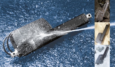
Photo 1: The new Thomson Electrak HD electric actuator was designed for mobile off-highway vehicle applications demanding the maximum available resistance to solids, liquids, extreme temperatures, shock, vibration, corrosion and electromagnetic interference.
Protection from solid objects and liquids
One of the greatest environmental threats to an electric actuator is penetration from both solid objects, such as dust and dirt, and liquids. In outdoor applications, this could be everything from rain, sleet and snow to a high-temperature, high-pressure wash down at the end of a long day of work in a field or construction site. The global standard for measuring protection from the ingress of solid objects and liquids is the International Protection Marking, or IP Code. The IP rating system was developed to specify the degree of environmental protection an enclosure provides against foreign materials that could impact performance. Industrial actuators use the IP rating system to determine the degree of environmental protection required for survival in specific applications.
The IP rating is composed of two numbers (Table 1). The first number represents resistance to solids and the second to liquids. An IP rating of 00, for example, means there is no protection from solids or liquids. An IP rating of 11 means protection from ingress by objects larger than 50mm and from rain or condensation. An IP rating of 66 means protection from penetration by particulates the size of dust and from high-pressure water jets from any direction.
Table 1: Degrees of Protection by Enclosures (International Electrotechnical Commission [IEC] 60529).
|
First digit: |
Second digit: |
|
|
0 |
No protection |
No protection |
|
1 |
Protected against solid objects over 50mm (e.g. hands, large tools). |
Protected against vertically falling drops of water or condensation. |
|
2 |
Protected against solid objects over 12.5mm (e.g. hands, large tools). |
Protected against falling drops of water if the case is disposed up to 15° from vertical. |
|
3 |
Protected against solid objects over 2.5mm (e.g. wire, small tools). |
Protected against sprays of water from any direction, even if the case is disposed up to 60° from vertical. |
|
4 |
Protected against solid objects over 1.0mm (e.g. wires). |
Protected against splash water from any direction. |
|
5 |
Limited protection against dust ingress |
Protected against low-pressure water jets from any direction. Limited ingress permitted. |
|
6 |
Totally protected against dust ingress. |
Protected against high-pressure water jets from any direction. Limited ingress permitted. |
|
7 |
N/A |
Protected against short periods of immersion in water. |
|
8 |
N/A |
Protected against long, durable periods of immersion in water. |
|
9K |
N/A |
Protected against close-range, high-pressure, high-temperature spray down |
To test a system for water resistance, specialists would refer to the published test specifications for volume, pressure, temperature and distance of the water for each rating and flood the actuator in all three planes following the specification. To test resistance to high-pressure wash down, they might expose it to 100 bar (1450 psi) at a distance of 0.1 to 0.15 meters on all planes. After each test, the specialist will disassemble the actuator looking for evidence of ingress of water.
Standard tests of this sort are typically done on static systems, but greater reliability can be achieved by observing performance under IP test conditions when the actuator is in dynamic operation or in motion. Thus, it is important to know not only that a static actuator can withstand a pressure wash, but also that it remains well-protected when operating outside in the rain. In an inadequately sealed actuator, for example, because the extension tube is in motion, the internal pressure can vary, causing it to act like a syringe, pulling in rainwater. This could compromise the electronics and damage the unit. This vulnerability would not show on a static test but would show in dynamic testing.
Achieving a higher IP rating is mostly a function of sealing strategy. Every component should be sealed, including motor mounts. Wipers, seals and gaskets are integral to successfully achieving IP ratings. The wiper brushes off contaminants from the extension tube during operation and is the first line of defense to water intrusion. The seals back up the wipers to complete the protection. Gaskets provide sealing between housings, cover tubes, motors and rear mounting components.


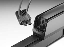
Photo 2: The IP69K rating for the new Thomson Electrak HD actuator comes, in part, from seals and gaskets incorporated into the cable connector.
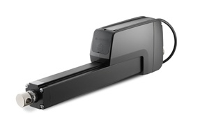
Photo 3: Extension tube wipers and housing gaskets protect the Thomson Electrak HD actuator mechanics and onboard electronics from both contaminants and water intrusion.
Protection from extreme temperature:
In recent years, there has been a trend to expand the operational temperature range for many outdoor applications. Temperatures from -40°F (-40°C) to 185°F (85°C) is a new standard for agriculture and construction vehicle applications. The low end of the standard assures performance in the coldest of climates. The higher temperature range would not only ensure operation in the warmest climates on Earth but also gives system designers mounting flexibility such as in or near an engine compartment.
One of the most widely applied temperature testing standards is EN60068-2-1 and EN60068-2-2. European Standards (EN) are being ratified by one of the three European Standards Organizations, CEN, CENELEC or ETSI. To pass the test for low temperature operation, a device must operate at rated load for 96 hours while thermal soaked at -40°F (-40°C). Likewise, to pass the test for high temperature operation, a device must operate at rated load for 72 hours while thermal soaked at 185°F (85°C). Some manufacturers may choose to exceed the number of hours in a test based on market demands. Thomson, for example, tests to 96 hours instead of 72 hours in an effort to further ensure safe operation at the extreme temperature levels.
Actuators also must be able to pass such tests after immediate and dramatic temperature variations that might occur when mounted in a high-temperature location and getting splashed with cold water. Other conditions might include operating at full-rated load and duty cycle and getting washed down with cold water. An example in the other extreme would be an actuator mounted to construction equipment used in cold climates and getting pressure-washed with high-temp water at the end of the day, especially if the actuator had not been used and was cold soaked.
The incorporation of onboard electronics, in addition to requiring environmental protection, also contributes to protection from extreme temperatures. Whereas protection from overheating traditionally has been provided with a thermal breaker inside the motor, that protection now is embedded in the circuit board. The thermal protection on the circuit board protects both the motor and the board from overheating and allows the actuator to complete the stroke before shutting down. The traditional breaker on the motor will stop the actuator anywhere in the stroke if overheating occurs. The electronics also include thermal compensation at low temperature, allowing the actuator to draw the higher current required at low temps without nuisance tripping,
Protection from operational shock
The latest shock testing profiles cover housings, structural bolts and any printed circuit assemblies/sensors included in the product. Guided by the EN60068-2-27 test standard, the test for operational shock involves 100 operations of 400 m/s², 6 ms duration shock pulses, which should be repeated in each of three mutually perpendicular axes.
EN60068-2-32 defines testing for drop shock. It details dropping a device onto a steel or concrete floor from a 1000mm platform in both directions of each axis and repeating that for a minimum of six drops.
Protection from random vibration
In addition to being able to withstand thermal shock, off-highway equipment must be able to perform effectively amidst constant vibration. Test protocols, usually OEM-specific, are run to ensure that the actuators will be able to withstand challenging vibration profiles.
Testing is conducted with the unit not powered or operating and mounted on vibration equipment guided by the power spectral density levels shown in Table 2. The actuator being tested should extend half of the stroke length and be tested in three orthogonal axes for 24 hours each.
|
Frequency Range (Hz) |
PSD (m/s2)2/Hz |
|
10 |
1.44 |
|
100 |
3.85 |
|
1000 |
3.85 |
|
2000 |
0.96 |
Table 2: Acceptable Frequencies at Various Power Spectral Density Levels.
The larger components on the printed circuit board are mechanically secured to the board and cushioned for high shock or vibration environments. These components typically fail without the added support in high-vibration or shock situations.
Protection from corrosion
Salt water immersion and salt spray can be a major source of corrosion in the many off-highway applications associated with shipping or other at-sea operations. ASTM B117-11 is a test standard for salt water, which says that a device should be able to withstand a certain number of hours of salt spray and be operational at the end of the test with no ingress of the salt spray. It is up to the manufacturer of the tested equipment to determine the duration of the test based on their specific market demands. Thomson, for example, tests their electric linear actuators to 500 hours.
Other common sources of corrosion include hydrocarbons, urea and fertilizers. One of the most widely applied standards for chemical resistance is ISO 15003, which provides design requirements and guidance for the manufacturers of electrical equipment used in mobile agricultural machinery, forest machinery, landscaping and gardening machinery. It provides test protocols for specific environmental conditions and defines severity levels for extreme environmental conditions that might occur during typical operations.
Testing for chemical resistance requires the ability to withstand three days of operation amidst a list of chemical concentrations defined by the manufacturer of the tested components based on their specific market demands. The following is an example used by Thomson for electric actuators commonly used on farm and construction equipment:
- Diesel Fuel – 100%
- Hydraulic Oil – 100%
- Brake Oil – 100%
- Ethylene Glycol – 50% aqueous solution
- Urea Nitrogen – saturated solution
- NPK Fertilizer*9 (7.5% each N, P, K) – saturated solution
Other standards applied to corrosion resistance, particularly Diesel Exhaust Fluid (DEF) are DIN 70070-05, AUS 32, ISO 22241-1.
Protection from voltage variation
Voltage variation can result from weak batteries, faulty voltage regulators, long wiring runs, corroded wiring connections and poor grounding. The latest electric linear actuators, such as the Thomson Electrak HD, are tested vigorously to withstand voltage levels for which they are designed as well as for voltage spikes, reverses in polarity and short circuits.
Testing to ensure that an actuator can accept its minimum and maximum operational voltage levels without causing damage involves demonstrating that it can withstand a defined amount of voltage for a specified time period. For example, a 12V DC actuator should be able to operate at between 9V DC and 16V DC for five minutes. An actuator rated for 24V DC should be able to operate at between 18V DC and 32V DC for five minutes. It’s important to note that these are simply tests run at the end limits. The unit also must work indefinitely between these values (Table 3).
|
|
12V DC |
24V DC |
|
Low Voltage |
9V DC |
18V DC |
|
High Voltage |
16V DC |
32V DC |
|
Time Duration |
5 minutes |
5 minutes |
Table 3: Acceptable Operational Voltage Ranges.
To ensure an actuator can handle accidental operational voltage spikes without damage, a 12V DC actuator should be tested to handle spikes to 26V DC for five minutes. Likewise, a 24V DC actuator should be tested to handle 36V DC for five minutes (Table 4).
|
|
12V DC |
24V DC |
|
High Voltage |
26V DC |
36V DC |
|
Time Duration |
5 minutes |
5 minutes |
Table 4: Acceptable Operation Over Voltage.
To ensure that the actuator would survive polarity reverses, a 12V DC actuator should be able to withstand minus 26V DC operation for 5 minutes while at 24V DC actuator should be able to withstand minus 36V DC for 5 minutes (Table 5).
|
|
12V DC |
24V DC |
|
High Voltage |
-26V DC |
-36V DC |
|
Time Duration |
5 minutes |
5 minutes |
Table 5: Acceptable Polarity Reverse Range.
Short circuits and electrostatic discharge (ESD) can contribute to damage in outdoor operations. The ASAE EP455 test standard covers short circuit testing, while ISO 10605 provides ESD testing procedures.
Protection from electromagnetic interference and transient surges
Printed circuit boards are subject to electromagnetic interference (EMI) and transient surges from a wide variety of sources. ISO 13766 and ISO 7637-2 are the most important standards providing testing guidelines for EMI and electrical transients. The following are among the test protocols they offer:
- Conducted Emissions - ISO 13766 (EMI/EMC Tests)
- Radiated Emissions - ISO 13766 (EMI/EMC Tests)
- Electromagnetic Immunity - ISO 13766 (EMI/EMC Tests)
- Inductive Load Switching - ISO 7637-2 (Electrical Transients)
- Cranking - ISO 7637-2 (Electrical Transients)
- Load Dump - ISO 7637-2 (Electrical Transients)
- Positive Inductance Transient Test - ISO 7637-2 (Electrical Transients)
- Positive and Negative Coupling Test - ISO 7637-2 (Electrical Transients)
Confidence in the field
While no testing protocol can guarantee 100% protection from all possible environmental assaults, the measures suggested above have been developed from a combination of the most stringent OEM requirements and related testing protocols as developed by leading industry organizations. The greater the compliance to these standards, the greater the electromechanical actuator will be protected from the environment it’s operating in.
Also, in addition to looking for compliance with company and industry-defined standards, look for the following design features, which support environmental protection and standards compliance:
- Overall mating of components
- Comprehensive sealing of all components, including motor and leads
- Enhanced wiper design
- Stainless steel extension tube
- Robust zinc enclosures with E-coating
- Hard anodized aluminum cover tubes
- Vibration-resistant electronics such as printed circuit board and potentiometer
Diligent attention to standards and related design features will help promote compliance, boost flexibility in the design process and provide confidence that you are doing everything that can be done to secure safe and reliable protection from the elements.


