Reduce Your Linear Motion Assemblies to a Single Component with Motorized Lead Screw Actuators
Julian Anton, Thomson Industries, Inc. and Chris Diak, Motion Industries
When it comes to specifying linear motion within a machine, system designers have many options from which to choose. Making the right choice can impact the ease of installation, footprint and cost of operation. A common driving mechanism for achieving linear motion is a stepper motor and externally supported lead screw-based assembly. A simpler, easier-to-install approach, however, is to select a drive mechanism with built-in guidance and support, thus removing the need for external components that would normally perform these functions and the complexity that comes with them.
Obtaining linear motion the traditional way
The core components of a traditional stepper motor and lead screw-based driving mechanism are the following:
• Stepper motor
• Motor to lead screw coupler
• Lead screw
• Lead nut
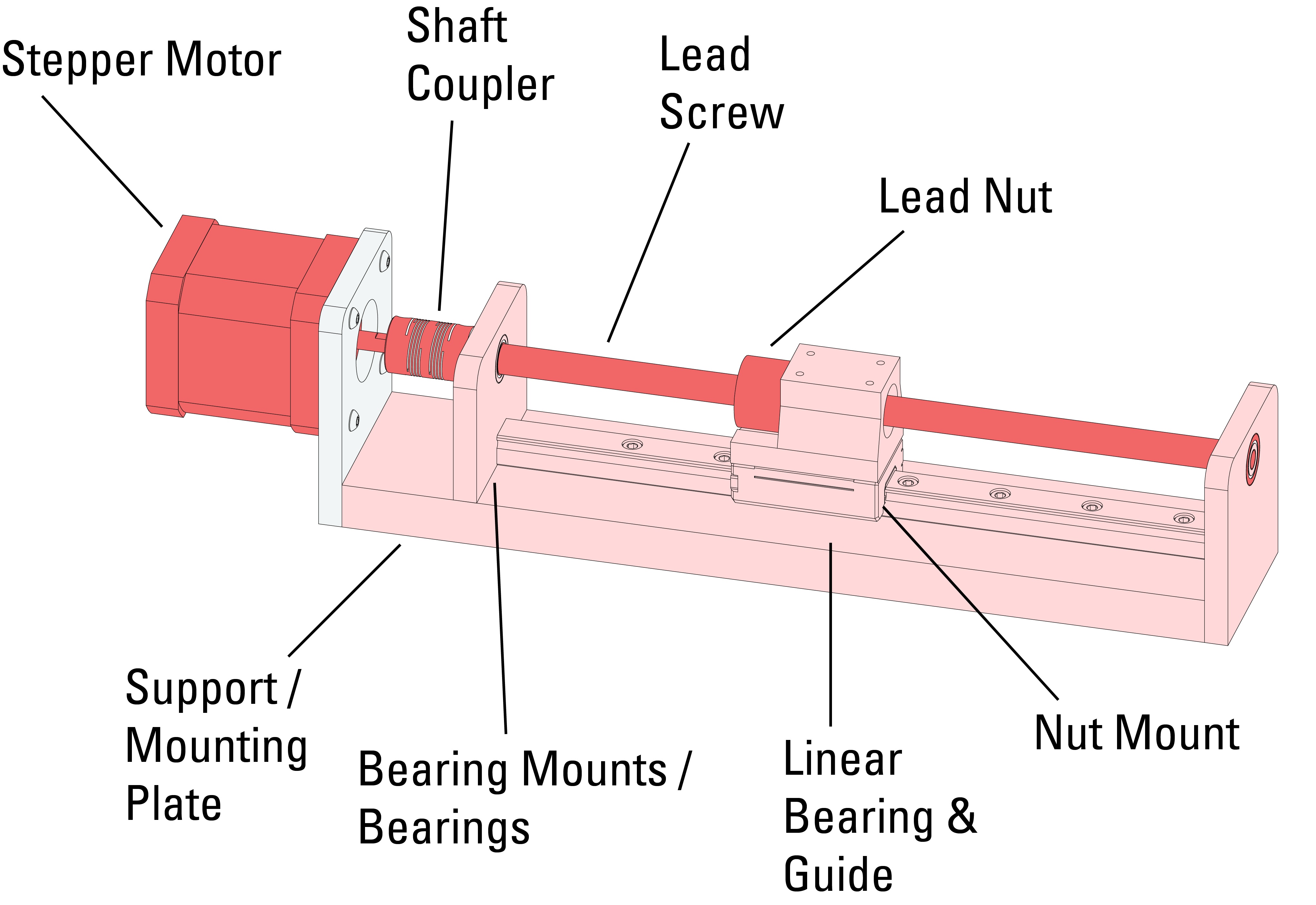
For this core to support a load and induce motion, however, additional components are required, including, for example, radial bearings and bearing mounts, linear bearings and guides, and mounting plates for all components. (Figure 1)
In these traditional mechanisms, powering on the motor usually produces motion by rotating the motor shaft that is coupled to a lead screw, causing it to rotate as well. The rotating lead screw then engages the lead nut that is attached to the load, and if it is properly supported and guided as shown in Figure 1, the nut and load translate axially across the lead screw.

Figure 1. A traditional stepper motor and lead screw-based drive mechanism. Linear bearing and guide components not only provide guidance for the lead nut but also support the load attached to the lead nut. (Image courtesy of Thomson Industries, Inc.)
Downside of external guidance and supports
While external assemblies can secure the nut effectively, there are drawbacks to this design approach. Primarily, the high component count contributes to a longer and more complex installation process. Installation is a challenge when utilizing external supports and guides because it is absolutely critical to ensure alignment is nearly perfect between all mating components. For proper motion to occur, all corresponding components will need to be carefully and properly positioned and secured. For example, if the lead screw and linear guides are not parallel with one another in both axes, there is a high likelihood of binding occurring, causing the entire drive mechanism to stall out.
In addition to a tedious and time-consuming installation process, prior to installation, a proper sizing and selection exercise to select the appropriate external guides and supports must be completed. Undersizing guides and supports can lead to premature failure of the entire mechanism, and oversizing can bring a significant increase in overall assembly cost and weight.
A third potential drawback of utilizing external guidance and supports is that the lead screw, lead nut, linear bearings and guides are completely exposed to the environment, which introduces the risk of contamination. Whether it is to prevent outside contaminants from penetrating the surfaces of the lead screw/lead nut and causing excess friction or to protect from wear debris generated by the sliding nut and leaking out in the overall system, a proper barrier is important.
A simplified solution
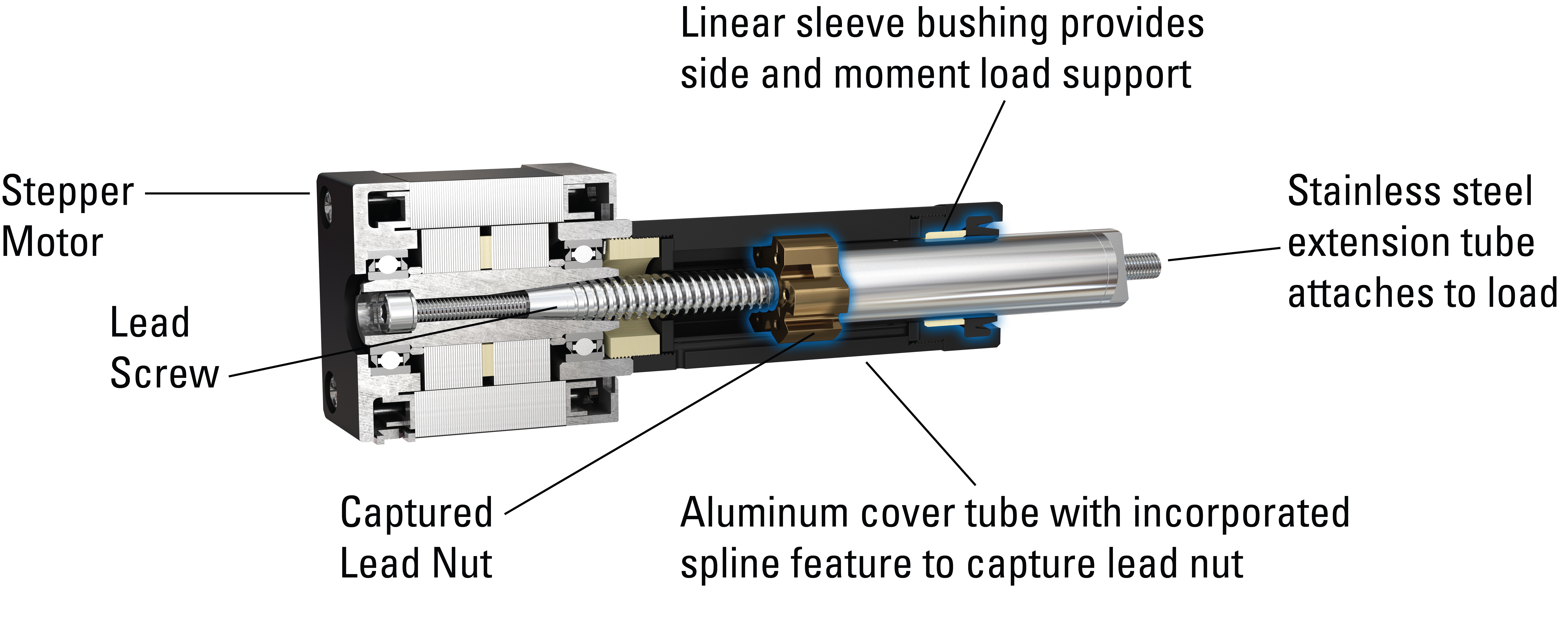
Designers of applications requiring shorter strokes with minimal radial and moment loads can avoid the drawbacks of the lead screw-based assemblies by choosing motorized lead screw actuator (MLA) -based drive mechanisms that integrate the guidance and support directly within itself. (Figure 2) This design choice completely eliminates the need for cumbersome external guidance and support.

Figure 2: Motorized lead screw actuator (MLA) with integrated linear guidance and support. (Image courtesy of Thomson Industries, Inc.)
MLAs enforce guidance by utilizing a splined cover tube that completely captures the mating lead nut and prevents rotation, while allowing axial translation. The integrated linear sleeve bushing within the end-cap at the front of the cover tube provides radial and moment load support.
A configuration like this offers many potential benefits to both the design engineer and the machine builder. As mentioned above, integrating support and guidance directly into the MLA unit significantly reduces complexity and time of installation. Instead of having to install and tediously align external guides and supports with the drive mechanism, a simple MLA can be utilized.
Also, if particulate contamination is of concern, use of an actuator eliminates the need for an outside protective barrier because the MLA unit has the lead screw, lead nut, guide and support completely housed within the cover tube.
Comparing traditional and MLA configurations in two sample applications
If the conditions are right, MLAs can be a simple and elegant driving mechanism for linear motion assemblies. The following sections highlight ideal applications where MLAs can offer a considerable benefit.
Comparing drive options for medical fluid pumping
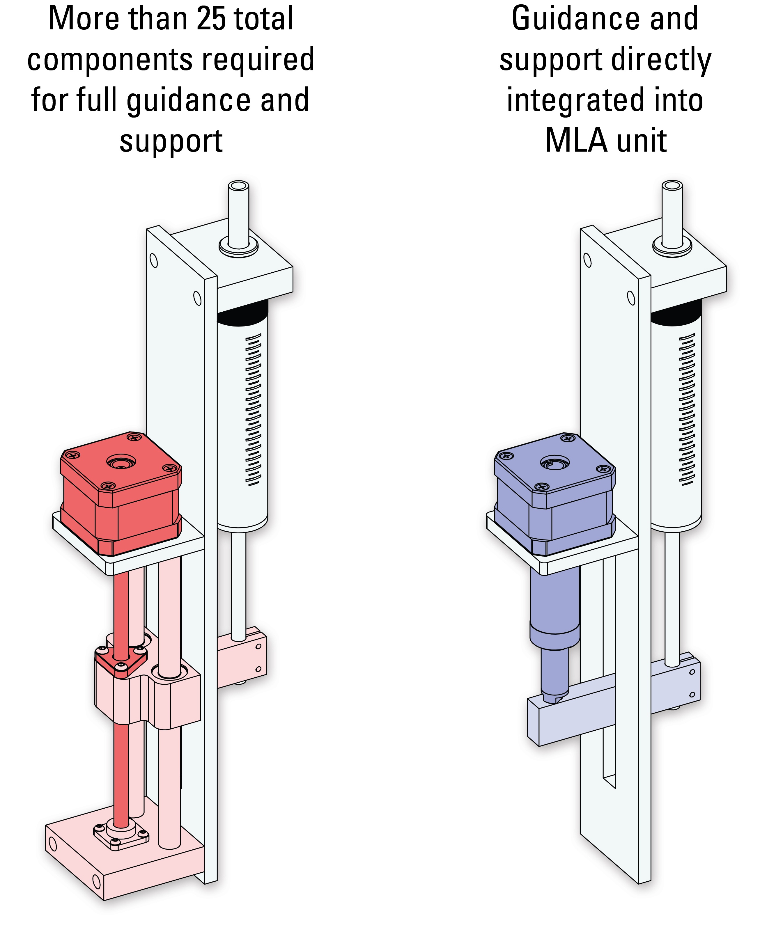
In a medical or laboratory environment, fluid pumps are commonly used to accurately deliver fluids into a patient’s body or test tubes for mixing or analysis. This fluid is usually expelled from a syringe reservoir by actuating a piston attached to a linear drive mechanism. Although not optimal, a traditional stepper motor and lead screw-based drive mechanism with external guidance and supports can accomplish this movement (Figure 3a).
However, since fluid pumps must often fit within space-constricted areas, minimizing components and shrinking the drive mechanism’s footprint can be of great value. MLAs improve fluid pumping in such applications by removing the need for external guides and supports that could consume valuable real estate within the machine where the pump is placed (Figure 3b). As MLAs have a completely self-contained guidance and support, the component count and simplicity of the fluid pump assembly can be dramatically improved. (Table 1)
Furthermore, because fluid pumps are used primarily in hygienic areas, the sealed enclosures of the MLAs prevent contamination from either entering or leaving the system.

(Image courtesy of Thomson Industries, Inc.) (Image courtesy of Thomson Industries, Inc.)
| Figure 3a: Fluid pump utilizing a traditional integrated stepper motor and lead screw-based drive mechanism with external guides and support. | Figure 3b: Fluid pump utilizing an MLA as the drive mechanism. |
Table 1: Comparing stepper motor lead screw integration options for fluid pumping
| Traditional stepper motor lead screw integration option | MLA option | |
| Total component count | 25+ | 2 |
| Approximate installation time (minutes) | 90+ | 5 |
Comparing Drive Options for Liquid Handling and Pipetting
A liquid handler is a multipurpose machine intended to sample, mix and combine liquid samples automatically. Fully automated workflows simplify repetitive fluid dispensing tasks. These operations require a pipette to dispense fluids into sample locations such as test tubes. The motion often requires complex guidance and support structure. (Figure 4a)

(Image courtesy of Thomson Industries, Inc.) (Image courtesy of Thomson Industries, Inc.)
| Figure 4a: Traditional stepper motor lead screw requires a profile rail guide and corresponding carriage assembly to translate axial motion. | Figure 4b: MLA assembly eliminates the need for external guidance and support. |
For such applications, designers prefer simpler and more compact drive mechanisms, which an MLA can provide. The pipetting motion itself is rather simple, and the loads tend to be very light, making it an ideal candidate for an MLA drive mechanism. And because the guidance and support are directly integrated within the MLA unit, the need for external guidance and support components is eliminated, thus reducing the component count and dramatically simplifying the pipetting sub-assembly. (Table 2) The enclosed system of the MLA is also well-suited to the purity of the laboratory environment.
Table 2. Comparing drive options for vertical pipetting applications
| Traditional stepper motor lead screw integration option | Motorized lead screw actuator (MLA) option | |
| Total component count | 30+ | 8 |
| Approximate installation time (minutes) | 120+ | 5 |
Selecting the right drive mechanism
In addition to fluid pumping and liquid handling, other applications in which MLAs offer advantages can include vertical plate or surface adjustment, pipetting, microscope slide positioning, proportional valve control and monitor/screen tilting. Considering the following factors will help determine whether an MLA option would be a good fit for a specific application.
Motion parameters.
MLAs are most suitable for applications requiring strokes of less than 2.5 inches (63 mm); moderate loads (up to 200 lbf or 90 kgf for larger motors), and speeds from approximately 0.5 in/s (13 mm/s) for low leads to approximately 8 in/s (200 mm/s) for higher leads.
Side and moment load handling.
While most stepper motor and lead screw-based drive mechanisms can handle considerable axial load, if side and moment loads are present, guidance and support from linear bearings, guides and supports will be required. However, if the side and moment loads are light enough — up to approximately 10% of axial load capacity of the motor — the integrated guidance and support design of an MLA is sufficient.
Simplicity.
If reducing component count and simplifying are priorities, designers can benefit from a fully integrated MLA configuration, removing the need for complex external guidance and support components.
Installation.
Reducing component count simplifies installation, dramatically shortening total assembly time. Instead of having to mount external linear guides, linear bearings and mounts, and having to carefully align them, installers can simply mount a single MLA unit that has all guidance and support directly integrated within the unit. MLAs traditionally come with a standard NEMA motor bolt hole mounting pattern, making them easy to install as a near drop-in replacement to previous stepper motor-based drive mechanisms.
Enviromental.
Systems used in hospitals, laboratories, clean rooms and other settings where contamination is of concern also benefit greatly from the sealed, all-in-one, unit.
Customization.
If none of the available offerings meet your needs, you may consider working with your vendor to create a custom option that does. Most vendors offer options to customize motor windings, encoders, cabling and connectors, end mounting, linear travel per step, and stroke lengths.
An overall simplier solution
MLAs may not be suitable for all applications. However, for those with the right motion parameters, side and moment load handling needs, simplicity preferences, and installation requirements, specifying MLAs brings numerous benefits for designers. Instead of having to design the external guidance and support assembly, they can specify a single drive unit with anti-rotational guidance and support built in. This solution would reduce double-digit component counts down to a single part number. Alternatively, with multiple, externally integrated components, there is a greater risk for system failure and extended process downtime, while parts are located and repairs made. Having only a single component to deal with, chances of failure are lower and the time required for repair is shorter. Another benefit of MLA technology is reduction in installation time from over an hour to mere minutes, which decreases associated labor costs. Because there is only one primary part, it saves the time needed to size and align multiple components necessary in an equivalent system. Finally, being enclosed, this type of product is packaged to provide improved environmental protection – thus sealing the deal on a better solution for your application.
Julian Anton is Design Engineer, Thomson Industries, Inc., and is responsible for new product design and development for lead screws and stepper motor linear actuators. He earned his Bachelor of Science in Mechanical Engineering from San José State University. Anton has been with Thomson for 6 years.
Chris Diak is the Automation Product Sales Manager at Motion Industries and has worked in the electrical/automation field for 24 years, with the last 22 at Motion. He earned a Bachelor of Science in Electrical Engineering from Clemson University.
For more information, visit MotionIndustries.com/pte, or view the MiHow2 video, “How to Install and Align a Ball Screw Assembly and Profile Rail” (https://tinyurl.com/y5wproem).


