Thomson Linear Motion Optmized

Stepper Motor Linear Actuators - Selection
Product Details
When selecting components for a new SMLA system build, ultimately experience is the best tool at one’s disposal. There are many preferences system designers have when it comes to PLCs, motion controllers, drives, etc., and there is no single correct setup. However, there are some general guidelines that can be used, which are outlined in the following sections.
SMLA Selection
When selecting the appropriate SMLA for your requirements, there are many factors to consider such as load and speed, available drive current and voltage, preferred configuration (MLS, MLN or MLA) and so on. Depending on the system requirements, the motor within the SMLA can be programmed to the desired speed, acceleration and general motion profile required. The main consideration is that the appropriate motor size is selected for the desired load and speed requirements. Individual motor performance plots can be found within the SMLA brochure and should be examined. Typically, a margin of at least 50% is recommended when sizing a motor. For critical and/or detailed sizing, discuss your requirements with a Thomson engineer
PLC, PC or Micro-controller Selection
Selection of a CPU is completely up to the system designer. Often, an existing PLC, PC or micro-controller within your system can utilized. If starting from scratch, you can ask yourself the following questions: Will the CPU be exposed to harsh industrial conditions where a PLC may be beneficial? Will I be writing my own software where utilizing a PC would make things easier? Or would integrating this CPU onto a circuit board and a small-scale micro-controller make the most sense?
Motion Controller and Driver Selection
Motion Controller
The first thing that should be checked when selecting a motion controller is compatibility with other system components such as the PLC/PC, stepper driver and voltage sources. Motor speed is controlled by the pulse rate (pulses per second) supplied by the driver via the controller. Depending on the speed required, one must ensure that the motion controller can output the corresponding pulse rate to reach that speed. The motion controller must be able to output this pulse rate, and the stepper drive must be able to receive this pulse rate and send over to the SMLA. The equation for determining required pulse rate is shown below.

- Linear speed: desired linear travel speed (in/s)
- Lead: lead screw travel per one full revolution of the screw (in/rev)
- Motor steps per rev: how many steps per one full revolution of the motor (steps/rev). All SMLAs are 200 steps per revolution.
- Pulses per step: pulses per step (pulse/step). SMLAs are 1 pulse per 1 step.
- Microstep: Micro-stepping resolution (micro-step/step)
Stepper Drive
Like a controller, the user should select a drive based on its ability to interface with all other components in the system – specifically the stepper motor and controller. For Thomson standard SMLA stepper motors, a drive must be able to allow the connection of a four-wire, bipolar motor. Electrical properties of the system must also be taken into consideration. Items such as desired output current to the motor, max input voltage from the power supply, and motor inductance will need to be reviewed. Just like a controller, required pulse rate will also need to be considered to ensure the driver is capable of driving the motor to the required speed.
Micro-stepping
There are many unique stepper motor drives out there that offer various micro-stepping resolutions. Depending on your requirement, micro-stepping may be worth considering, specifically if a smooth motion is required. Micro-stepping essentially takes the standard 200 steps per revolution of the SMLA motor and breaks down each step to smaller increments such as from ½ step, ¼ step and even all the way to 1/256 step. the figure below illustrates the difference between full-stepping and micro-stepping.
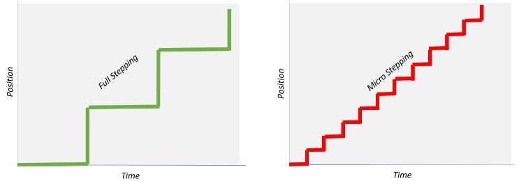
comparing the motion between full-stepping and micro-stepping
An important thing to note about micro-stepping is that it does not improve positional accuracy by going to finer resolutions. A typical rotational accuracy for a stepper motor is approximately +/- 0.09 degrees regardless of micro-stepping resolution.
Final Considerations
The guidance provided above should be utilized as a way of getting in the ballpark for a system build. Some experimentation with trial and error may need to be conducted to get a completely functional system. Always utilize the help of an experienced system designer and add a decent margin to system calculations when possible. Thomson can help recommend a SMLA product to get the performance you need. PLC, motion controller and drive manufacturers will also have dedicated engineers to help assist you in selecting one of their products.