Thomson Linear Motion Optmized

Choose Your Login Account
Thomson currently has two account systems - one for the website and CAD model downloads, and one for e-commerce. We understand that two logins is an inconvenience and are working to consolidate our systems into one login process. Until we’re able to consolidate the two logins, please follow these guidelines:
Website Login
- Download CAD models
- Save and retrieve projects in LinearMotioneering® and MicronMotioneering® tools
- Access Distributor Extranet and all related resources
E-commerce Login
- Order directly from Thomson online (North America only)
- Authorized Thomson Distributors can view and order from quotes online (Global)
- View the shopping cart and look up prior direct orders
CLOSE
Customer Service Chat (ONLINE) Customer Service Chat (OFFLINE)

Compact Linear Systems
Take the guesswork out of specifying multiple components for your linear motion designs. Thomson compact linear systems address the need for thrust and bearing support in a single, small-scale unit for space-conscious applications. Whether you opt for one of our three standard architectures (see below) or work with our engineers on a “from scratch” solution, your application requirements will determine the selection and sizing of your system components.
Find a Product


Select Product Type
New!
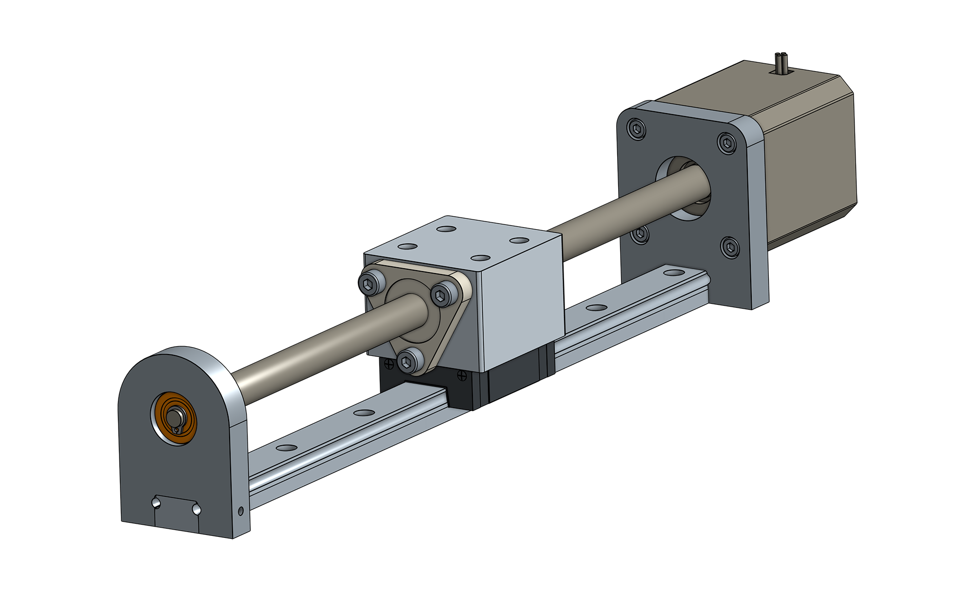
Narrow Configuration
Allows for a more narrow footprint by stacking the lead screw and profile rail bearing vertically.
New!
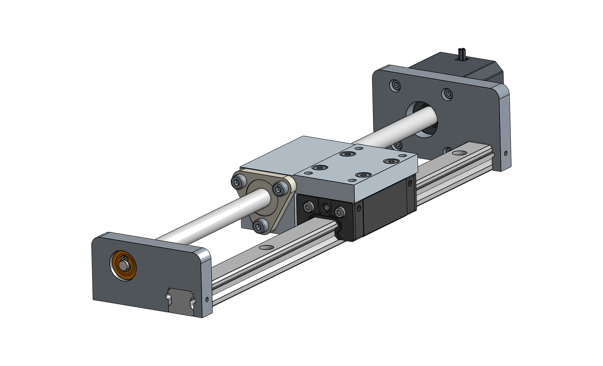
Wide Configuration
Allows for a lower profile footprint by arranging the lead screw and profile rail bearing horizontally.
New!
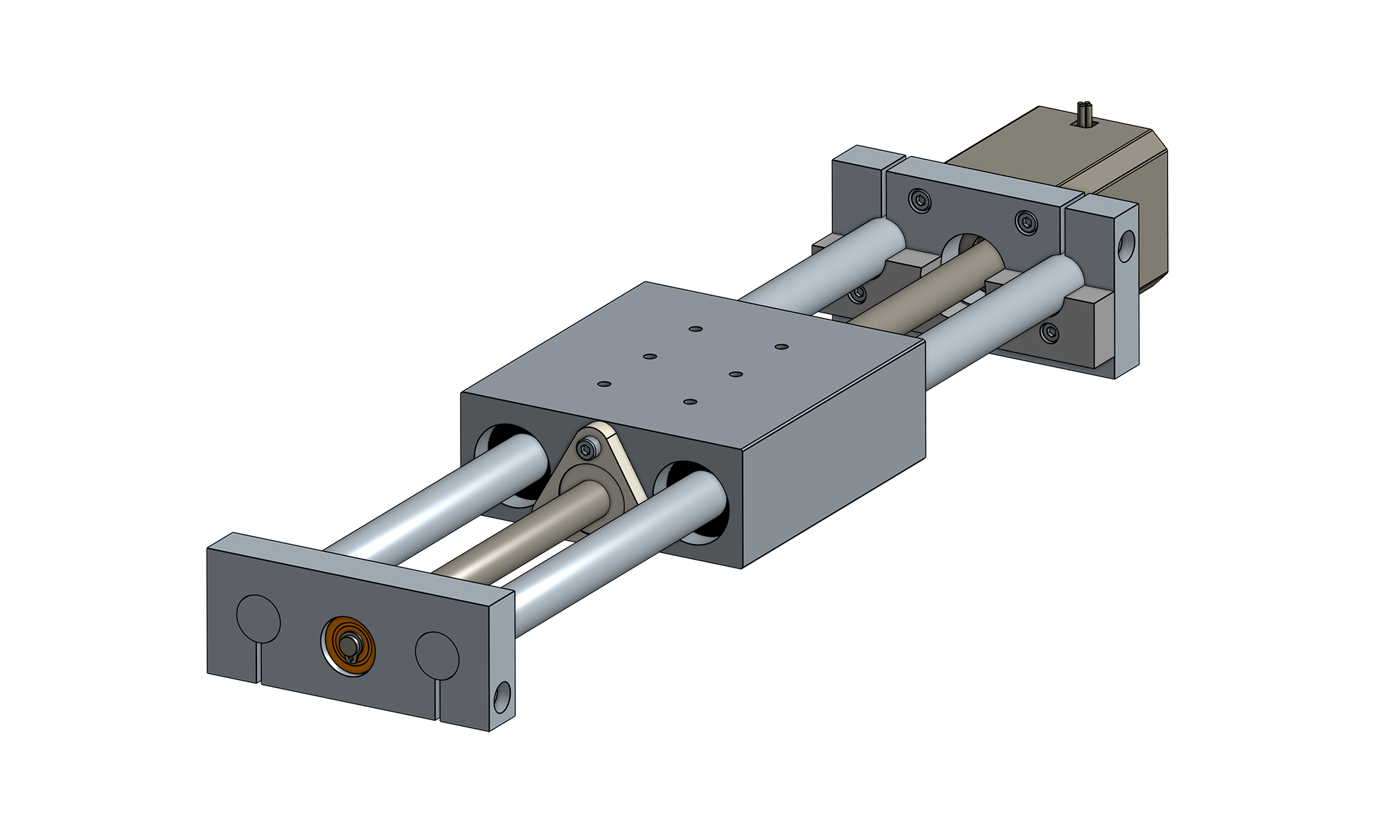
Round Rail Configuration
A dual round rail, low profile footprint enables an easy to install, cost-effective solution with higher moment load capacity.
Schedule virtual design consultation
Create a unit from scratch along-side a Thomson engineer. Mix and match Thomson components for a solution tailored to your application.
 Examples of applications
Forces Referencing Diagram
NEMA 14
35mm x 35mm (1.4" x 1.4") square face capable of thrust loads (Fx) up to 222 N (49 lbs)
NEMA 17
42mm x 42mm (1.7" x 1.7") square face capable of thrust loads (Fx) up to 334 N (75 lbs)
NEMA 23
57mm x 57mm (2.3" x 2.3") square face capable of thrust loads (Fx) up to 535N (120 lbs)
Forces Referencing Diagram
NEMA 17
42mm x 42mm (1.7" x 1.7") square face capable of thrust loads (Fx) up to 334 N (75 lbs)
NEMA 23
57mm x 57mm (2.3" x 2.3") square face capable of thrust loads (Fx) up to 535N (120 lbs)
Forces Referencing Diagram
NEMA 17
42mm x 42mm (1.7" x 1.7") square face capable of thrust loads (Fx) up to 334 N (75 lbs)
NEMA 23
57mm x 57mm (2.3" x 2.3") square face capable of thrust loads (Fx) up to 535N (120 lbs)
Forces Referencing Diagram
Microguide Size 9
Max load capacities: Fy = 250 N (56 lbf), Fz = 200 N (44 lbf), Mx = 10 Nm (7 lbf·ft), My = 5 Nm (3 lbf·ft), Mz = 5 Nm (3 lbf·ft)
Microguide Size 12
Max load capacities: Fy = 284 N (63 lbf), Fz = 500 N (112 lbf), Mx = 11 Nm (8 lbf·ft), My = 6 Nm (4 lbf·ft), Mz = 6 Nm (4 lbf·ft)
Forces Referencing Diagram
Microguide Size 12
Max load capacities: Fy = 284 N (63 lbf), Fz = 500 N (112 lbf), Mx = 11 Nm (8 lbf·ft), My = 6 Nm (4 lbf·ft), Mz = 6 Nm (4 lbf·ft)
Microguide Size 15
Max load capacities: Fy = 583 N (131 lbf), Fz = 1250 N (281 lbf), Mx = 22 Nm (16 lbf·ft), My = 12 Nm (8 lbf·ft), Mz = 13 Nm (9 lbf·ft)
400 Series Size 15
Max load capacities: Fy = 1254 N (281 lbf), Fz = 2000 N (449 lbf), Mx = 48 Nm (35 lbf·ft), My = 41 Nm (30 lbf·ft), Mz = 41 Nm (30 lbf·ft)
Forces Referencing Diagram
Left Orientation
Orientation with bearing on the left side of the lead screw. Max payload capacities: Fy = 2000 N (449 lbf), Fz = 2000 N (449 lbf), Mx = 48 Nm (35 lbf·ft), My = 41 Nm (30 lbf·ft), Mz = 41 Nm (30 lbf·ft)
Right Orientation
Orientation with bearing on the right side of the lead screw. Max payload capacities: Fy = 2000 N (449 lbf), Fz = 2000 N (449 lbf), Mx = 48 Nm (35 lbf·ft), My = 41 Nm (30 lbf·ft), Mz = 41 Nm (30 lbf·ft)
Forces Referencing Diagram
Super 6
Max payload capacities: Fy = 200 N (44 lbf), Fz = 200 N (44 lbf), Mx = 12 Nm (8 lbf·ft), My = 7 Nm (5 lbf·ft), Mz = 7 Nm (5 lbf·ft)
Super 8
Max payload capacities: Fy = 400 N (89 lbf), Fz = 400 N (89 lbf), Mx = 26 Nm (19 lbf·ft), My = 19 Nm (14 lbf·ft), Mz = 19 Nm (14 lbf·ft)
Super Smart 8
Max payload capacities: Fy = 500 N (112 lbf), Fz = 500 N (112 lbf), Mx = 33 Nm (24 lbf·ft), My = 24 Nm (17 lbf·ft), Mz = 24 Nm (17 lbf·ft)
Standard Backlash
Clearance between screws and nut of up to 0.25 mm (0.010 in)
Anti-Backlash
Preloaded nuts with no play between the screw and nut.
Standard Backlash
Clearance between screws and nut of up to 0.25 mm (0.010 in)
Anti-Backlash
Preloaded nuts with no play between the screw and nut.
Standard Backlash
Clearance between screws and nut of up to 0.25 mm (0.010 in)
Anti-Backlash
Preloaded nuts with no play between the screw and nut.
Standard Backlash
Clearance between screws and nut of up to 0.25 mm (0.010 in)
Anti-Backlash
Preloaded nuts with no play between the screw and nut.
Standard Backlash
Clearance between screws and nut of up to 0.25 mm (0.010 in)
Anti-Backlash
Preloaded nuts with no play between the screw and nut.
Standard Backlash
Clearance between screws and nut of up to 0.25 mm (0.010 in)
Anti-Backlash
Preloaded nuts with no play between the screw and nut.
Standard Backlash
Clearance between screws and nut of up to 0.25 mm (0.010 in)
Anti-Backlash
Preloaded nuts with no play between the screw and nut.
Standard Backlash
Clearance between screws and nut of up to 0.25 mm (0.010 in)
Anti-Backlash
Preloaded nuts with no play between the screw and nut.
Standard Backlash
Clearance between screws and nut of up to 0.25 mm (0.010 in)
Anti-Backlash
Preloaded nuts with no play between the screw and nut.
Standard Backlash
Clearance between screws and nut of up to 0.25 mm (0.010 in)
Anti-Backlash
Preloaded nuts with no play between the screw and nut.
Standard Backlash
Clearance between screws and nut of up to 0.25 mm (0.010 in)
Anti-Backlash
Preloaded nuts with no play between the screw and nut.
Standard Backlash
Clearance between screws and nut of up to 0.25 mm (0.010 in)
Anti-Backlash
Preloaded nuts with no play between the screw and nut.
Standard Backlash
Clearance between screws and nut of up to 0.25 mm (0.010 in)
Anti-Backlash
Preloaded nuts with no play between the screw and nut.
Standard Backlash
Clearance between screws and nut of up to 0.25 mm (0.010 in)
Anti-Backlash
Preloaded nuts with no play between the screw and nut.
Standard Backlash
Clearance between screws and nut of up to 0.25 mm (0.010 in)
Anti-Backlash
Preloaded nuts with no play between the screw and nut.
Standard Backlash
Clearance between screws and nut of up to 0.25 mm (0.010 in)
Anti-Backlash
Preloaded nuts with no play between the screw and nut.
Standard Backlash
Clearance between screws and nut of up to 0.25 mm (0.010 in)
Anti-Backlash
Preloaded nuts with no play between the screw and nut.
View Loading Diagram
View Loading Diagram
Examples of applications
XY Stages
Optimize XY stage designs with compact linear systems’ compactness and power.
Pipetting
Tiny, precise and repeatable vertical motion is essential for pipetting. Choose compact linear systems to simplify your z-axis and for accurate horizontal motion.
Fluid Pumps
Compact linear systems can increase pump pressure, reduce equipment footprint and more accurately disperse fluid.
Examples of applications
View Loading Diagram
Overview

Standard Compact Linear Systems

Narrow Configuration
This architecture allows for a smaller footprint by vertically stacking the screw and profile rail bearing.

Wide Configuration
This architecture allows for a shorter system height by horizontally arranging the lead screw and profile rail bearing.

Build a Custom System
Schedule a virtual design consultation
Work with a Thomson engineer to mix and match components for a solution tailor-made to your application.
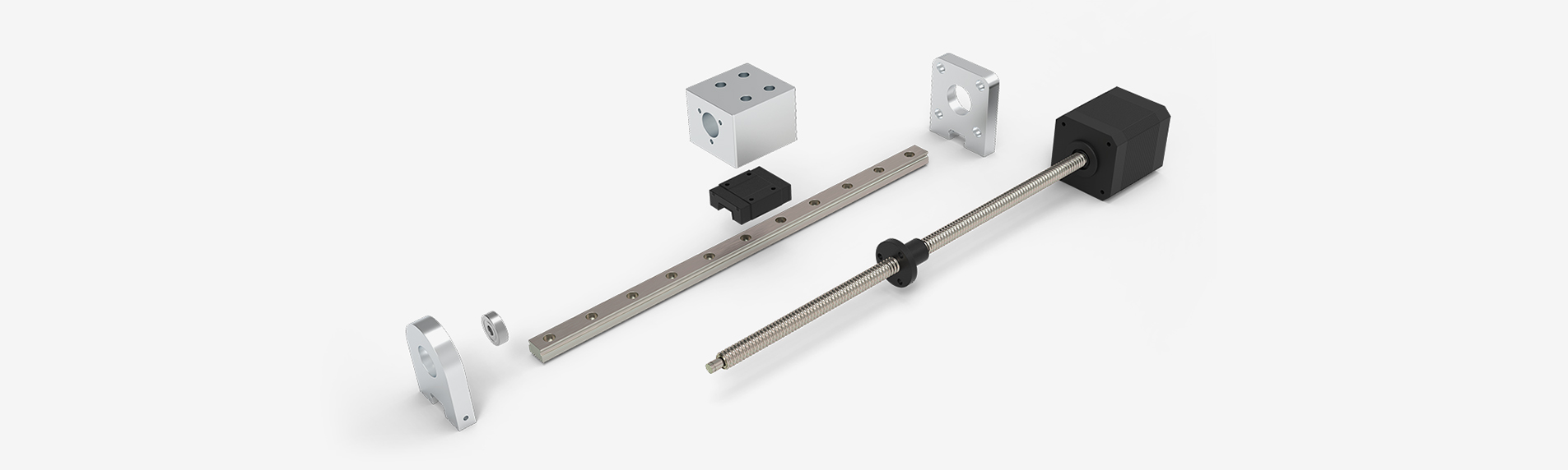
Schedule a Virtual Design ConsultationAnatomy of a Compact Linear Systems
| Basic Specifications | |||
|---|---|---|---|
| Lead Screw | |||
| Material | 300 Series Stainless Steel | ||
| Standard Coating1 | None | ||
|
Standard Lead Accuracy
[in./ft. (µm/300 mm)]
|
0.010 (250) | ||
|
Precision Lead Accuracy
[in./ft. (µm/300 mm)]
|
0.003 (75) | ||
|
Straightness
[in./ft. (µm/300 mm)]
|
0.005 (125) | ||
| Lead Nut | |||
| Standard Material | Internally lubricated acetal | ||
|
Nut Efficiency2
[%]
|
Up to 85 | ||
|
Typical Linear Travel Life
[in. (km)]
|
10 x 106 (250) | ||
|
Positional Repeatability with Standard Nut3
[in. (mm)]
|
0.005 to 0.010(0.127 to 0.254) | ||
|
Positional Repeatability with Anti-Backlash Nut4
[in. (mm)]
|
<0.002 (0.051) | ||
| Motor | |||
| Frame Size | NEMA 14 | NEMA 14 | NEMA 14 |
|
Step Size
[°]
|
1.8 | ||
|
Concentricity of Mounting Pilot to Shaft
[in. (mm)]
|
0.003 (0.08) TIR | ||
|
Perpendicularity of Shaft to Mounting Face
[in. (mm)]
|
0.003 (0.08) TIR | ||
|
Max. Case Temperature
[°F (°C)]
|
176 (80) | ||
|
Storage Temperature
[°F (°C)]
|
-4 to 122 (-20 to 50) | ||
|
Ambient Temperature
[°F (°C)]
|
-4 to 122 (-20 to 50) | ||
|
Max. humidity (non-condensing)
[%]
|
85 | ||
|
Magnet Wire Insulation
[°F (°C)]
|
Class B 130 (266) | ||
| Insulation Resistance | @ 500 VDC [Mohm] 100 | ||
| Dielectric Strength | for 1 min. [Vac] 500 | ||
| Assembly | |||
|
Max. Backlash with Standard Nut5
[in. (mm))]
|
0.010 (0.25) | ||
|
Operating Temperature
[°F (°C)]
|
15 to 125 (-10 to 50) | ||
- Contact Thomson for optional lead screw coatings.
- Depends on lead, nut material and lubrication.
- Depends on nut, load and orientation.
- For best positional repeatability, load should be kept well bellow design system.
- Nut fit can be adjusted depending on backlash requirements.
Compact Linear System Highlights:
- Choose from three standard architectures or build a “from scratch” system.
- Mounting blocks can be machined to virtually any shape or size.
- Virtual design consultations are like having a linear motion expert by your side as you build your solution.
- Systems can be produced and delivered quickly due to back-end modularity processes being automated.
- A 3D model of your system is made available to you in real time or typically within one business day.
Compact Linear Applications:
- Medical devices
- Security/Military
- Packaging
- Semiconductors
- 3D Printers
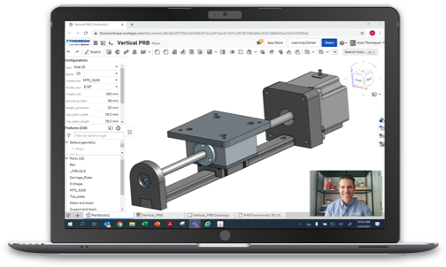
VIDEO: Tech Tips: How to Choose Your Ideal Compact Linear System
Thomson compact linear systems can be purchased in pre-designed configurations, or you can fully customize them at no additional cost. This video shows you a couple ways to build the best system for your linear motion design.
CAD Models
-Compact Linear Systems 2D/3D Interactive Models
| Compact Linear Systems - Round Rail Configuration |  |
— | — |
| Compact Linear Systems - Narrow Configuration | |
— | — |
| Compact Linear Systems - Wide Configuration | |
— | — |
Literature
Brochures
| Compact Linear Systems | 8119 KB | |
| Compact Linear Systems | 8119 KB | |
| Compact Linear Systems | 1550 KB | |
| Miniature Components and Systems | 6871 KB | |
| Miniature Components and Systems | 6862 KB |
Manuals
| Compact Linear Systems Installation Manual | 910 KB | |
| Compact Linear Systems Installation Manual | 910 KB |
To provide better service to you on our websites, we and our service providers use cookies to collect your personal data when you browse. For information about our use of cookies and how to decline them or turn them off please read our cookie policy [available here].