By Julian Anton
Design Engineer – Lead Screws
Thomson Industries Inc.
www.thomsonlinear.com thomson@thomsonlinear.com
One of the most common mistakes a design engineer can make when selecting motors for lead screw applications is assuming that the way in which the motor and the screw are integrated does not matter. A properly integrated lead screw and motor can cut costs, boost performance, simplify maintenance and provide greater prototyping flexibility. Three of the most common approaches include implementing an external shaft coupling; permanently or semi-permanently fusing the lead screw and the motor shaft together; and using detachable connections. Here are some points to consider when comparing these options.
Exploring external shaft coupling connections
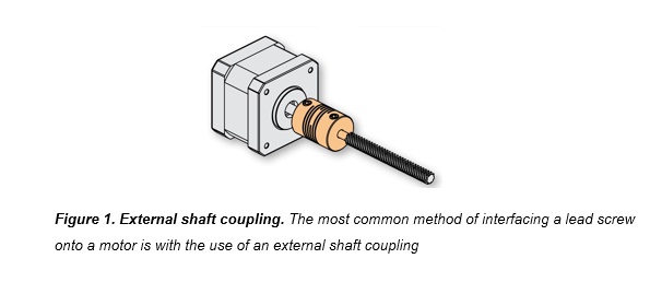
An external shaft coupling is the most common method for interfacing a lead screw and motor. As illustrated in Figure 1, this is a simple cylinder, which receives the motor shaft on one end and the lead screw on the other. It is relatively cost effective and can be disassembled for service, but there are also distinct disadvantages; reduced stroke length being the primary one.
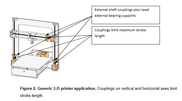
In the generic 3-D printer configuration shown in Figure 2, the external shaft couplings limit stroke length on both the vertical and horizontal axes, which ultimately decreases the overall volume of what the printer can produce within a given footprint. Other disadvantages of using an external shaft coupling include:
- The need for additional external bearings near the coupling to account for radial and axial support, further reducing available stroke length.
- Increased overall system inertia, resulting in a higher motor torque requirement.
- Increased system complexity due to additional fasteners, bearings and supports required.
- Increased system weight due to a higher number of components.
Examining Permanent Connections
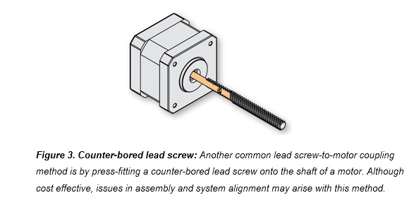
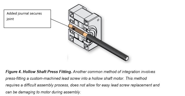
Directly joining the lead screw to the motor shaft can be a low-cost solution -- especially when considering individual component costs alone. Some manufacturers do this by building a motor in which the lead screw is at the end of the shaft. Others will machine features onto one end of the lead screw and mount directly onto the motor shaft (Figure 3), or conversely, they might mount a modified lead screw into a hollow shaft motor (Figure 4). The option of replacing the motor shaft with a lead screw can be cost effective but requires complex assembly, which must be done at a motor manufacturing facility. This method of integration also can be quite permanent. If there is an issue with either the lead screw or motor, the entire unit may need to be replaced.
Mounting a counter-bored lead screw onto a standard motor shaft, as illustrated in Figure 3, can be an inexpensive coupling method. Typically a machined knurl, adhesive and/or a cross-axial pin are used to further restrain the lead screw to the motor and limit the risk of detachment. Although this can provide an additional layer of protection, it complicates the assembly and permanently fixes the lead screw to the motor. This type of integration requires custom machining and high-precision assembly to prevent misalignment during mounting. Improper motor and lead screw alignment may introduce unwanted system vibration and potentially decrease motor performance.
Another common method for fixing a lead screw to a motor is inserting a modified lead screw into the hollow shaft of a custom motor, as shown in Figure 4. With this method, manufacturers will machine a journal to the end of a lead screw and insert it directly into the mating shaft. Although this type of assembly can yield more stroke length over other direct connect options, it still requires precision machining, proves difficult to assemble and can increase the risk of lead screw misalignment during assembly. This approach makes it difficult to replace the lead screw and to perform subsequent maintenance as needed since the lead screw is usually welded into place to prevent detachment. Also, during the delicate assembly process, manufacturers run the risk of damaging components within the motor.
Like the other permanently connected methods, this type of assembly also comes as a complete unit that would need to be replaced entirely if there are any individual component failures of the lead screw or motor. This can be a critical disadvantage at testing and prototyping when component flexibility can reduce costs and avoid delays in production schedules.
Examining Detachable Connections
Another connection option is a hybrid solution with a rapid-decoupling taper lock. The rapid-decoupling capability enables easy interchange of the motor or lead screw should one component need to be swapped out.
When considering a system with detachable components, attention to motor and lead screw alignment is critical. Poor alignment causes undesirable lead screw wobble (run out) and introduces vibrations that reduce motor torque, generate excess heat and produce noise.
Alignment must be addressed at the design phase. The Thomson taper-lock design (Figure 5), for example, is designed to maintain perfect alignment by using a self-centering conical socket and tapered shaft arrangement similar to that of the Morse taper, which has served the machine tool industry for many years.
Detachable connections have many advantages over traditional, permanently fixed solutions. They can reduce assembly time, simplify machine design, enable quick and easy prototyping, and drastically shorten maintenance time and costs. In addition to these benefits, they have a smaller impact on inventory by stocking only components rather than the more costly, fully integrated assemblies on hand.
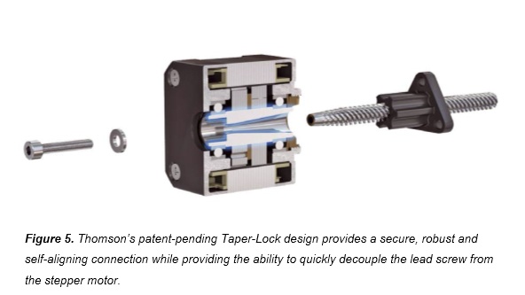
The taper-lock solution also removes the need for external couplings and support bearings, which will maximize stroke length while still having a self-aligning, interchangeable lead screw that is easy to assemble and maintain.
A detachable connection is especially valuable in application environments subject to heat, contamination or corrosion; or where an unprotected lead screw is likely to require more frequent replacement. A single motor can support multiple screw sizes, simplifying both prototyping and inventory management.
What’s right for you?
Design engineers have numerous integrated motor and lead screw assembly options. External shaft couplings can deliver acceptable thrust economy and some degree of maintainability but provide a limited stroke length and an increased overall footprint.
Joining the motor shaft and lead screw in more or less permanent arrangements can protect stroke length, deliver adequate thrust and offer some cost advantages. This approach can introduce lead screw run out and make it difficult, if not impossible, to change out lead screws during maintenance or prototyping. An architecture that supports interchangeable lead screws, self-alignment, maximum stroke length, application flexibility and cost-effective maintenance has the obvious advantage.
Answering the following questions can help you decide which option is right for you:
- Would any of your applications benefit from more stroke length?
- How often does the first prototype prove to meet your requirements?
- How often have you had to discard a complete motor and lead screw assembly when either the motor, lead screw or nut fails?
- How long does it take to replace a failed assembly?
- How often do your maintenance teams have to make a second or third trip to the field once the need for a replacement is identified?
- How often have you had problems with run out or noise?
- How much motor- and lead screw-related inventory do you maintain?
Your answers to these questions will help you decide whether your motorized lead screw needs are best served by external shafts or permanent, semi-permanent or detachable motorized lead screw components. The right choice can lower your cost of ownership, increase performance, simplify maintenance and provide greater flexibility when designing your product.
For more information on the range of motorized lead screws from Thomson, visit
www.thomsonlinear.com/mls or www.thomsonlinear.com/motorized.


