Thomson Linear Motion Optmized


Lead Screws - Nut - Pressure Velocity
Design and Theory
The Pressure Velocity (PV) limit is a key design parameter
in the proper sizing and selection of lead screw assemblies that use
polymer nuts. Although most engineering
polymers list a PV value, PV is generally overlooked when considering lead screw designs using polymer nuts. Surprisingly, most
designers simply look at the nut load rating when sizing their systems
and ignore the impact of speed. Exceeding the PV limit can cause the nut to deform from the heat generated and can lead to rapid and sudden
failure. This type of failure can be avoided by designing within the PV envelope.
The PV factor can be used to define the performance
envelope for a lead nut and screw assembly by using the
product of the pressure and velocity between nut and screw. The velocity
being the sliding speed between the nut and screw mating surfaces.
By substituting for pressure into the above formula then solving for axial force results in:
This formula can be used to plot the PV curve over a desired range of velocities. With velocity being in the denominator, higher speeds result in lower amounts of force that the nut will accept. The reverse is also true, as more force is applied, slower speeds are required to avoid
exceeding the nut’s PV limit. In order to prevent failure, the screw assemblies load and speed combination must be kept below the PV limit for the material of the nut.
Below is an
example PV plot for 2 similar nuts but made from different materials.
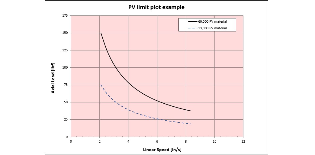
PV limit plot
Note: The the velocity in the plot has been adjusted from the surface velocity of the nut to screw interface to the linear speed of
the nut using the geometry of the nut helix.
PV limit plot
Note: The the velocity in the plot has been adjusted from the surface velocity of the nut to screw interface to the linear speed of
the nut using the geometry of the nut helix.
Temperature and duty cycle
The PV limit being when the nut will begin to deform from heat, the temperature and duty cycle of the application will also have an impact. Unfortunately it is difficult to predict the impact of temperature and duty cycle with a simple formula. For applications where the duty cycle is above 50% or the temperatures are above ambient, testing the assembly is the best way to find the performance limits.
For details on the calculations related to the PV limit for a specific nut read on. Otherwise feel free to advance to the next Topic.
Calculating PV limit for a specific nut
To calculate the acceptable load of a nut based on the nut material's PV value we need to calculate the projected area of engagement and surface velocity. Below we will look at each.
Area of engagement
In order to calculate the PV curve for a specific nut, the projected area of engagement between the threads of a nut and screw should be calculated. This is done by calculating the helix length in the nut and multiplying it by the number of starts. Then multiply by the depth of the thread engagement between the nut and screw.
Complications
A complicating factor arises in practice. When a load is applied the nut threads can deflect, reducing the nut to screw contact area.

Nut deflecting under load
Nut deflecting under load
The reduction in thread contact decreases the area of engagement. In practice it is difficult
to calculate exactly what this reduction in area will be. And more unfortunate is that the
area decreases as the load increases. Which compounds the tendency for PV
related failure. This underscores the need to stay within the performance
envelope.
To address this issue, a
correction factor (Cf) is introduced into to the projected area calculation. This factor
normally ranges from about .75 to .25 as the loading increase from light
to the full rated load capacity.
Surface velocity
Surface velocity can be calculated using the following formula