Installation
The successful integration of a Motorized Lead Screw in an application is primarily dependent on the screw alignment and subsequent screw runout. If incorrectly mounted, a lead screw assembly will have significantly reduced system life and may be noisy or inaccurate. Thomson methodically straightens all screws prior to assembly to minimize vibration and runout. The Taper-Lock coupling method also was designed to provide a concentric interface and optimize alignment. Proper alignment, end support configuration and lead nut selection are important factors to achieve a well designed installation that will exceed expectations.
Installation Step-by-Step
1. Select Motorized Lead Screw Configuration
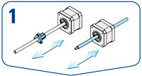
Determine which of the two types of configurations – rotating screw (S) or rotating nut (N) – the application requires. See page 3 and 5 of Thomson’s Motorized Lead Screw brochure for more information.
2. Select Motor Size
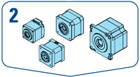
Select the appropriate size based on desired performance, motor frame size, etc. Thomson offers four base models (ML11, ML14, ML17 and ML23) with optional motor windings, linear travel and load capacity selection.
3. Select Lead Screw
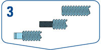
Select the lead screw diameter and length with regard to the required stroke of the application and the type of end machining the screw requires.
4. Select Nut
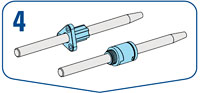
For rotating screw (S) configurations, choose between a standard or high performance nut as well a standard or antibacklash nut. Rotating nut (N) configurations as default always come with high performance nut and a standard backlash nut.
5. Mount the Motorized Lead Screw
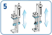
Mount the unit into the application using the tolerance guidelines shown on page 9 of Thomson's Motorized Lead Screw Brochure.


